Politetrafluoroetylen (PTFE)
Politetrafluoroetylen (PTFE) składa się z łańcucha węglowego, w którym każdy atom węgla połączony jest dwoma atomami fluorowymi. Całkowita fluoryzacja łańcucha węglowego, jak również siła wiązań węgiel – fluor czynią PTFE substancją niezwykle stabilną. Dzięki temu ten syntetyczny polimer, który jest nieresorbowalny, biologicznie i chemicznie obojętny jest idealnym materiałem w produktach medycznych. Poza bardzo długą historią zastosowań PTFE w sterowanej regeneracji tkanek, PTFE był również używany ponad 30 lat w zastosowaniach sercowo-naczyniowych, takich jak szwy, przeszczepy naczyniowe i zastawki serca.
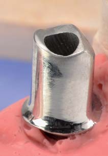
Porowaty PTFE (expanded PTFE, ePTFE)
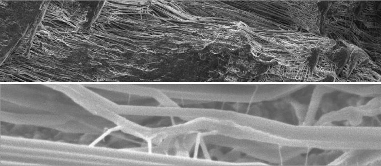
Porowaty PTFE (expanded PTFE, ePTFE) różni się stopniem porowatości zależnie od procesu produkcyjnego. Podgrzanie PTFE i przyłożenie siły rozszerza mikrostrukturę materiału do uzyskania porowatego PTFE (ePTFE). Pod elektronowym mikroskopem skaningowym (SEM), możemy dostrzec gęstą sieć węzłów połączonych przez włókna. Jeśli węzły i włókna są rozszerzone, porowatość materiału wzrasta.
ePTFE posiada długą historię sukcesów w procedurach sterowanej regeneracji tkanki (GTR), szczególnie w periodontologii. Jednakże, wysoka porowatość struktury ePTFE umożliwia penetrację bakterii, kiedy dojdzie do ekspozycji błony w jamie ustnej. Prowadzi to do wysokiego współczynnika infekcji i często wymaga wcześniejszego usunięcie błony. Poza tym, wysoce porowata struktura pozwala wrastać tkance miękkiej, co utrudnia usunięcie membrany i wiąże się z wykonaniem rozległego zabiegu. Membrana z ePTFE musi zostać całkowicie pokryta płatem podczas zabiegu i tylko w takich przypadkach daje dobre rezultaty. Nie nadaje się jednak do pokrywania zębodołów oraz innych przypadków, gdzie może dojść do jej ekspozycji.
Porowaty PTFE (ePTFE)
Na górze: powiększenie 500x
Na dole: powiększenie 20000x
Gęsty PTFE (dense PTFE, dPTFE)
Gęsty PTFE (dense PTFE, dPTFE) jest wytwarzany w taki sposób, aby wyeliminować powstawanie przestrzeni między węzłami i włóknami. W efekcie materiał posiada mikropory i tym samym jest nieprzepuszczalny dla bakterii umożliwiając jednocześnie dyfuzję gazów i małych molekuł. dPTFE został tak zaprojektowany, aby ekspozycja w środowisku jamy ustnej nie powodowała powikłań. Stanowi to udoskonalenie wcześniejszej wersji, czyli ePTFE i znajduje zastosowanie w wielu wskazaniach klinicznych, zwłaszcza w zachowaniu kształtu i objętości zębodołu poekstrakcyjnego, gdzie celowa ekspozycja błony oferuje kilka korzyści.
Po aplikacji membrany dPTFE i pokryciu płatem zostaje ona natychmiast pokryta białkami osoczowymi, co ułatwia adhezję komórkową do gładkiej, biokompatybilnej powierzchni. Ta adhezja komórkowa prowadzi do powstania hermetycznej warstwy, zapewniając barierę dla migrujących bakterii i komórek nabłonkowych wokół i pod, również wtedy gdy dojdzie do jej ekspozycji. Adsorpcja białek osocza ułatwia także dyfuzję rozpuszczalnych molekuł organicznych poprzez membranę. Usuwanie dPTFE jest łatwe ze względu na brak wrastania tkanek miękkich w strukturę membrany.
Tekstura membrany dPTFE powoduje zwiększenie jej powierzchni oraz stabilność membrany w obrębie tkanek miękkich. Ta stabilność z kolei minimalizuje ryzyko odsłaniania membrany oraz zmniejsza możliwość poruszenia się membrany. Główna zaleta membrany dPTFE polega na tym, że może ona pozostawać odsłonięta w środowisku jamy ustnej chroniąc jednocześnie biomateriał, który pokrywa. Błona jest miękka, elastyczna i łatwa do aplikacji. Całkowite pokrycie membrany nie jest obligatoryjne i przy pozostawieniu membrany częściowo odsłoniętej do jej usunięcia nie jest potrzebny zabieg. Jeżeli natomiast membrana zostaje pokryta płatem, do jej usunięcie w dalszym etapie wystarczy niewielkie nacięcie na grzbiecie wyrostka.
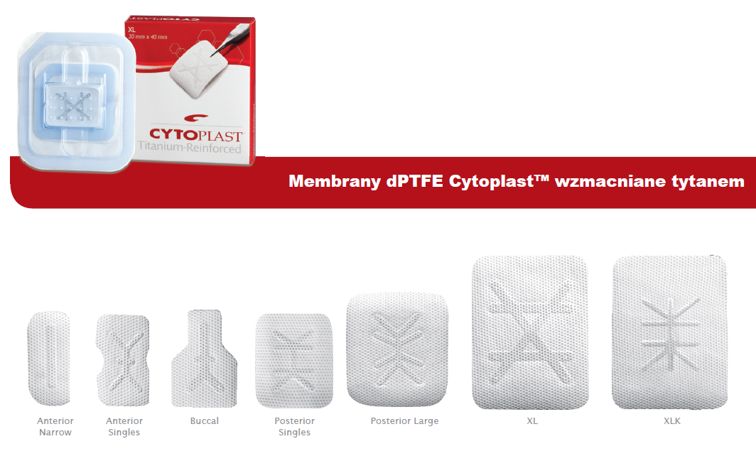
Membrany dPTFE są również dostępne w wersji ze wzmocnieniem tytanowym, co gwarantuje wzrost sztywności materiału. Membrany takie wykorzystuje się przy dużych ubytkach kostnych, gdzie dla odbudowy kości konieczne jest utrzymanie przestrzeni. Zatopiony tytanowy szkielet pozwala ukształtować błonę tak, aby pasowała do różnych defektów i po jej adaptacji i ukształtowaniu utrzymywała nadany kształt. Jest to konieczne przy dużych ubytkach kostnych, w szczególności do augmentacji pionowej.

Gęsty PTFE (dPTFE)
Na górze: powiększenie 500x
Na dole: powiększenie 20000x
Ewolucja membran PTFE
- Lata 80.: Firma Gore-tex® wytwarza membranę, która staje się złotym standardem w regeneracji kości.
- 1994: Zostaje wprowadzona na rynek membrana TefGen-FD®, która ma zachowywać swoje właściwości nawet przy ekspozycji
- 1997 do chwili obecnej: Membrana Cytoplast® wykonana z dPTFE staje się standardem i liderem na rynku, dzięki swoim właściwościom, łatwej procedurze usuwania membrany, dużej gamie rozmiarów i kształtów oraz wersji ze szkieletem tytanowym.
Unikalne właściwości dPTFE
Bariera dla bakterii:
Test bariery bakteriologicznej został wykonany w niezależnym laboratorium analitycznym zgodnie z nor-mami FDA. Celem testu było zweryfikowanie czy błony z dPTFE są nieprzepuszczalne dla bakterii. Wybrano bakterię E. faecalis jako mikro-organizm testowy z uwagi na jej naturalną obecność w środowisku jamy ustnej, jej sferyczną morfologię, szybki rozrost oraz mały rozmiar (0,5-1,0 μm).
Bakterie testowe zostały umieszczone na błonie dPTFE w stężeniu 2×10 na membranę. 10 próbek zostało umiejscowionych na płytce agarowej i inkubowanych przez 48h. Po inkubacji i usunięciu membran dokonano oceny ilości bakterii pod membranami. O ile wszędzie zanotowano wzrost ich liczby, to nie zarejestrowano wzrostu na płytkach pod membranami dPTFE.
Przyleganie komórek:
Wprawdzie PTFE nie jest podatnym na adhezję, komórki przylegają do zewnętrznej powierzchni błony dPTFE. Zdjęcia usuniętej membrany dPTFE wykonane w mikroskopie elektronowym wykazały przyleganie fibroblastów do powierzchni błon dPTFE. Ponadto usunięcie po okresie 21-28 dni odsłoniętej membrany, często prowadzi do niewielkiego krwawienia, co wskazuje na biologiczny „przyczep” do błony dPTFE. ”Przyczep” ten jest ważny dla stworzenia uszczelnienia przy krawędziach odsłoniętej błony dPTFE lub dla wspomagania zamknięcia rany w przypadku dużych augmentacji.
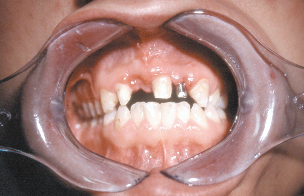
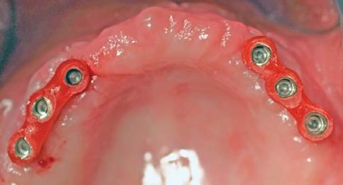
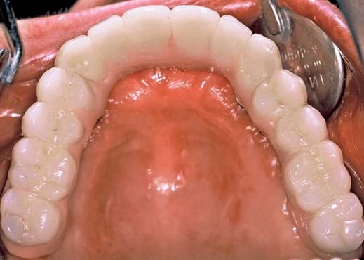
Technika zachowania zębodołu Cytoplast™
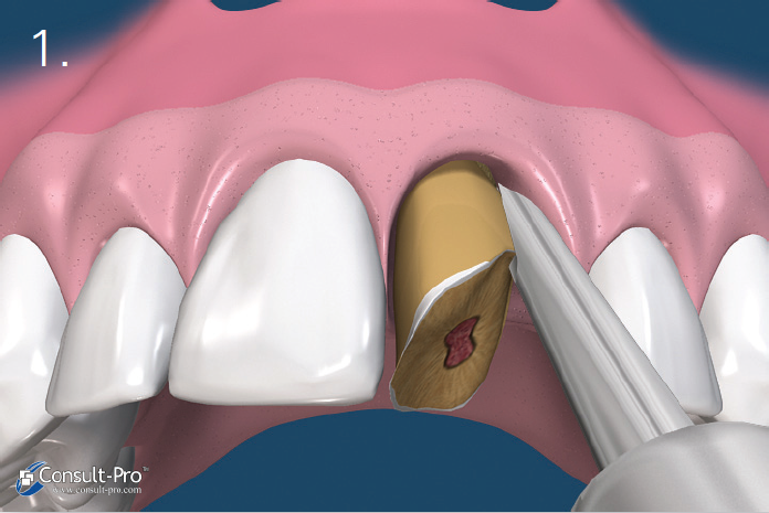
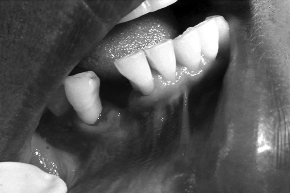
Ryc. 1. Zaleca się przeprowadzenie ekstrakcji w sposób minimalnie traumatyczny. Wskazane jest stosowanie periotomów lub sekcjonowanie zęba, tak aby podczas ekstrakcji zachować cienką blaszkę policzkową zębodołu. Wszystkie pozostałości tkanki miękkiej należy usunąć z wnętrza zębodołu. Szczególną uwagę należy zachować podczas czyszczenia okolicy wierzchołka zębów ze zmianami zapalnymi lub po leczeniu kanałowym. W zębodole powinno występować krwawienie a w przypadku jego braku zalecana jest dekortykacja, aby umożliwić szybką waskularyzację i dostęp komórek progenitorowych.
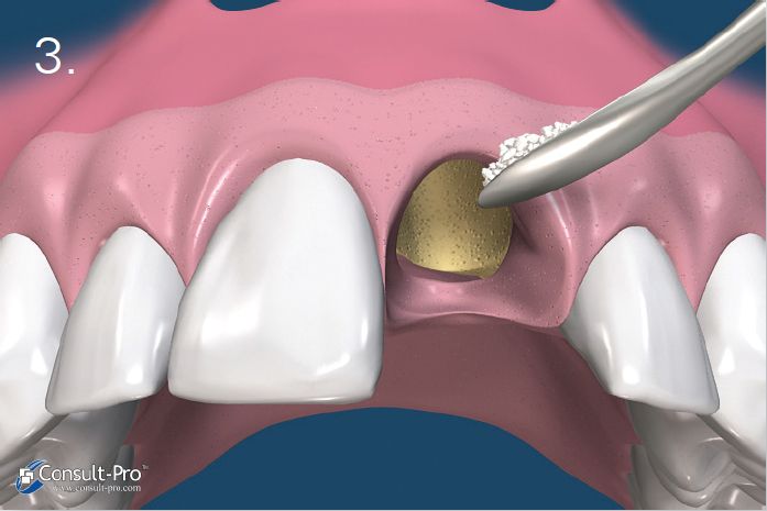
Ryc. 2. Za pomocą małego respatora lub kirety należy wytworzyć kieszonkę podokostnową 3-5 mm poniżej brzegu dziąsła lub poniżej krawędzi ubytku kostnego, zarówno od strony przedsionkowej jak i od strony jamy ustnej. W odcinku estetycznym nie zaleca się nacinania brodawek międzyzębowych, ale zastosowanie ww. techniki. Zaklinowanie membrany dPTFE nastąpi w wytworzonej raspatorem kieszonce podokostnowej.
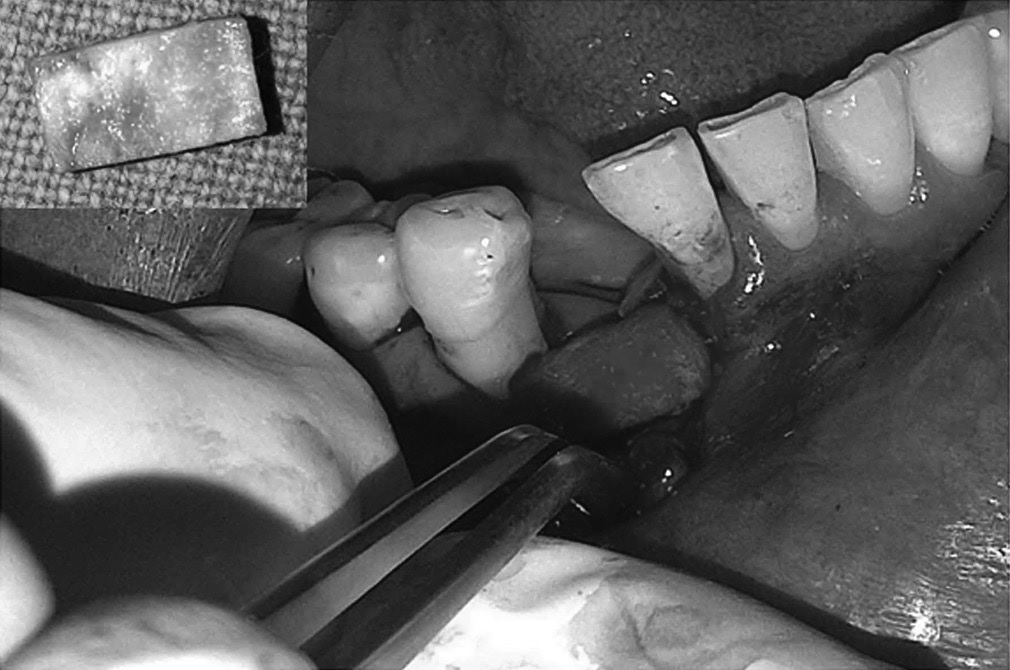
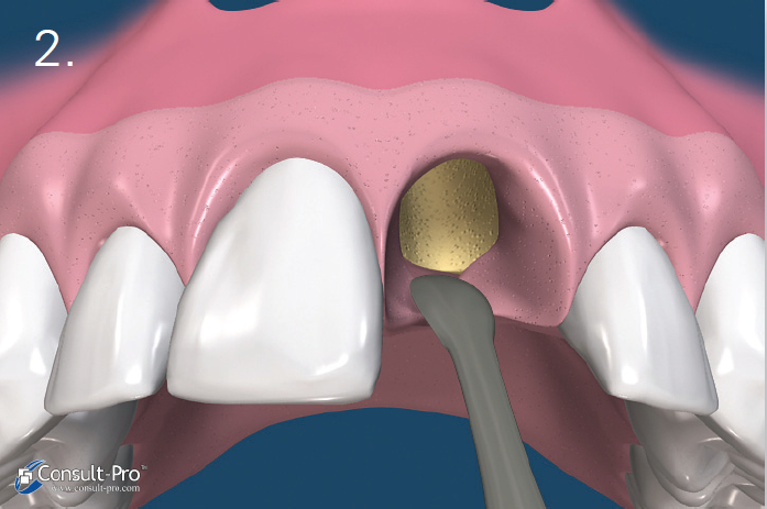
Ryc. 3-4. Granulki biomateriału wprowadzamy do zębodołu za pomocą łyżeczki lub specjalnego aplikatora. Należy się upewnić, że materiał jest równomiernie rozprowadzony w zębodole, ale bez nadmiernego ucisku. Gwarantuje to prawidłową neoangiogenezę i dalsze formowanie się kości.
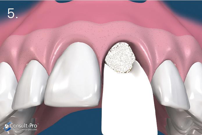

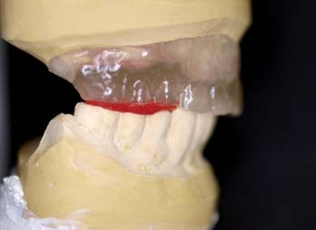
Ryc. 5-6. Błona dPTFE zostaje przycięta do takich rozmiarów, aby przekraczała o 3-5 mm krawędzie zębodołu po czym zostaje wprowadzona do stworzonej wcześniej kieszonki podokostnowej – od strony przedsionkowej, podniebiennej oraz pod brodawki międzyzębowe. Aby uzyskać stabilność membrany odwarstwienie płata powinno być minimalne.
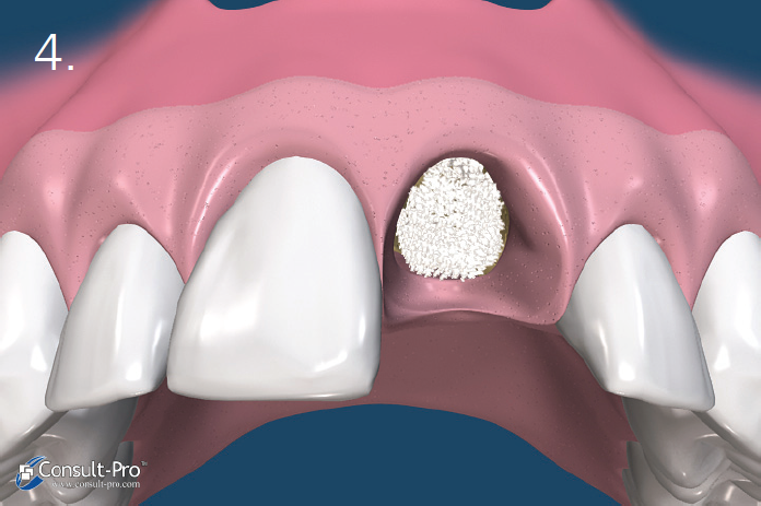
Przed rozpoczęciem szycia należy upewnić się czy membrana nie jest pofałdowana i leży całkowicie na powierzchni zębodołu. Należy usunąć wszelkie granulki biomateriału pozostałe pomiędzy membraną a dziąsłem. Trzeba również unikać perforowania membrany.
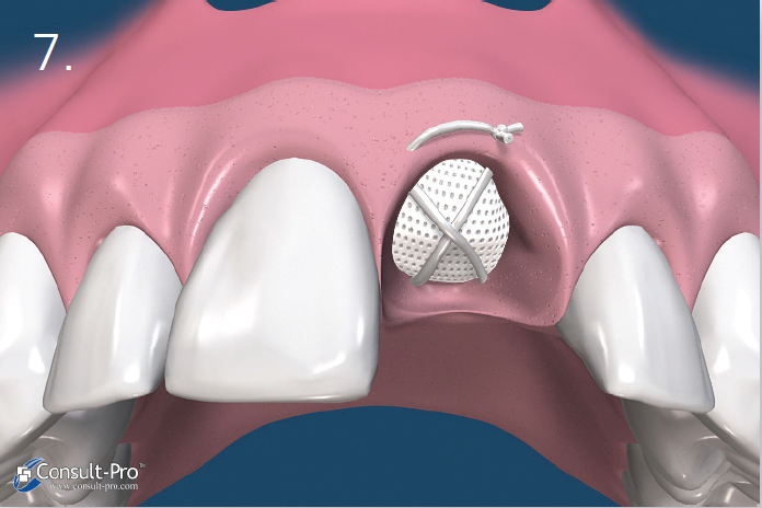
Ryc. 7. Membrana zostaje dodatkowo ustabilizowana przez zastosowanie szwu materacowego krzyżowego. Nie zaleca się natomiast przyszywania samej membrany lecz jej dociśnięcie szwami położonymi nad nią. Dodatkowo można założyć 1-2 szwy punktowe. Można stosować dowolny rodzaj szwów, ale najmniejszy efekt zapalny dają szwy wykonane z PTFE. Należy je pozostawić przez okres 10-14 dni.
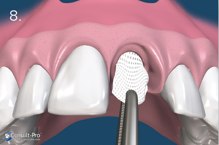
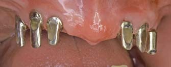
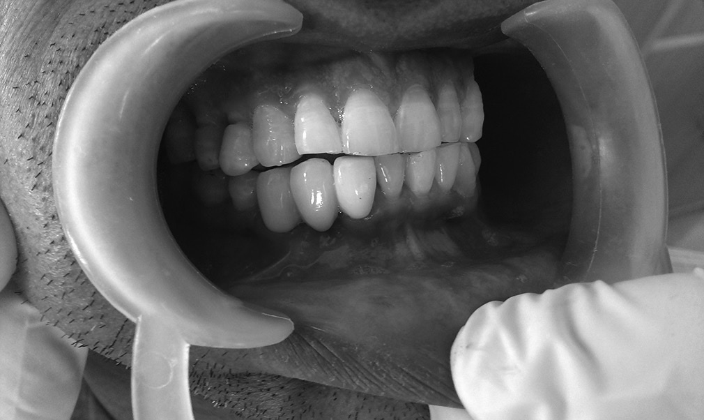
Ryc. 8. Błona zostaje usunięta po 21-28 dniach, bez konieczności zabiegu chirurgicznego. W przypadku, kiedy zębodół poekstrakcyjny miał zachowane wszystkie ścianki, membranę można usunąć już po 3 tygodniach. Badania pokazały, że po ok. 21-28 dniach w zębodole znajduje się gęsta, łącznotkankowa, bogato unaczyniona substancja natomiast w 2/3 dowierzchołkowych obserwujemy już zaczątki osteogenezy. W przypadku zębodołów z brakującymi lub uszkodzonymi ściankami, zaleca się dłuższe pozostawienie membrany. Do usunięcia membrany dPTFE wystarczy znieczulenie nasiękowe i wyciągnięcie membrany np. za pomocą igłotrzymacza.
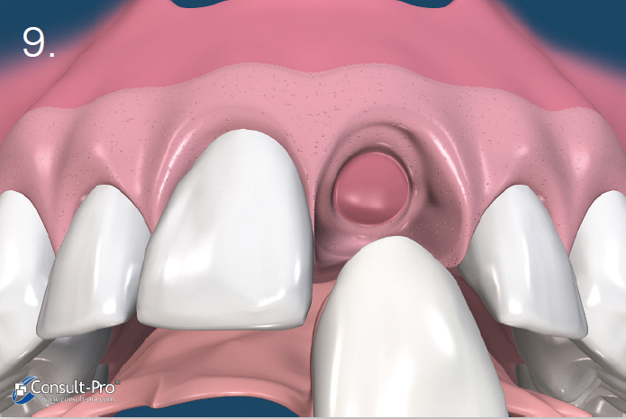
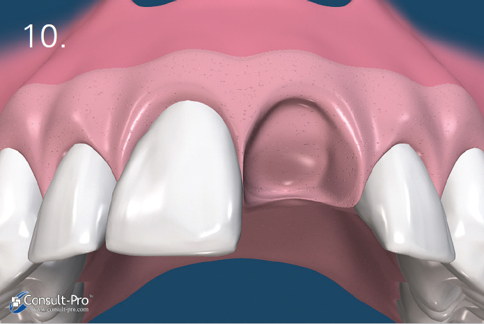
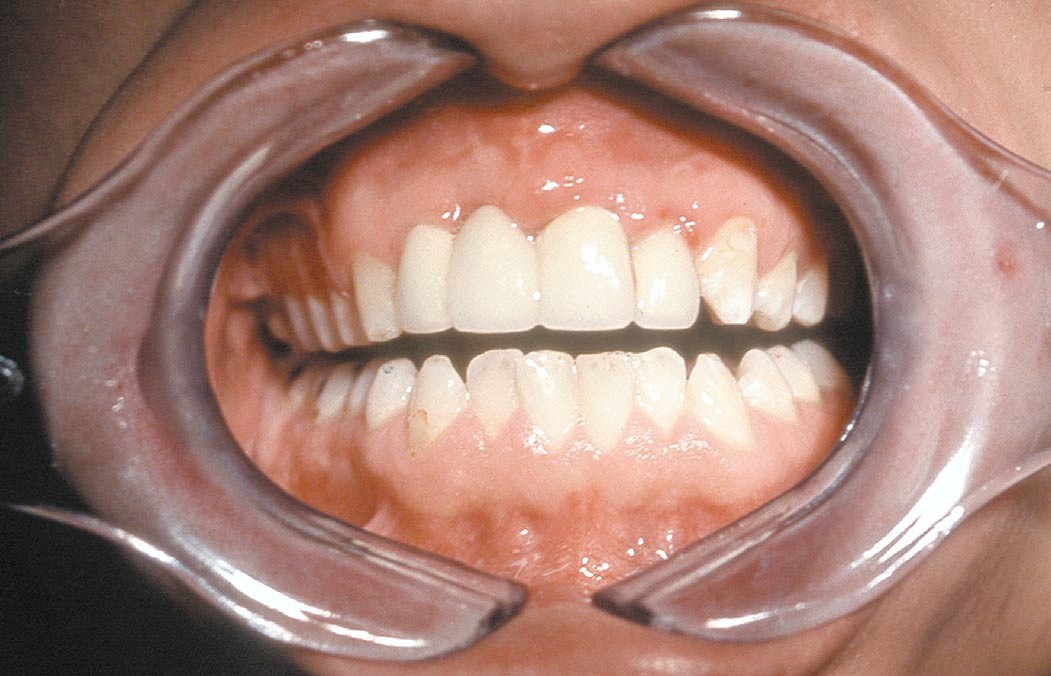
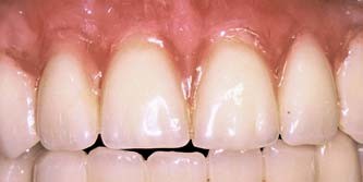
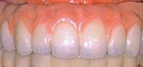
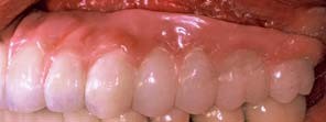
Ryc. 9-10. Po usunięciu membrany w zębodole możemy zauważyć bogato unaczynioną tkankę, którą stopniowo pokryje migrujący nabłonek. Po 6 tygodniach można zaobserwować tworzące się dziąsło rogowaciejące. W ten sposób zachowujemy naturalny wygląd dziąsła i brodawek międzyzębowych. W tym czasie w zębodole zaczyna tworzyć się tkanka kostna.
Badania kliniczne
Przewidywalność
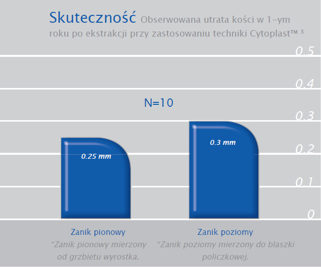
2 niezależne badania dotyczące łącznie 696 zębodołów pokestrakcyjnych z zastosowaniem techniki Cytoplast™ i membran dPTFE pozostawionych bez pokrycia płatem, pokazały brak jakiejkolwiek infekcji.

Sprawdź ofertę membran dPTFE Cytoplast [link]
Piśmiennictwo
- Yamashita M, Horita S, Takei N, Sasada Y, Shibato W, Ishikawa Y, Takao K, Maki K, Funakoshi E. Minimally Invasive Alveolar Ridge Preservation/Augmentation Procedure (Open Barrier Membrane Technique). Presented at the 2010 Research Forum Poster Session. Annual Meeting of the American Academy of Periodontology (AAP) in Honolulu, HI, October 30 – November 2, 2010.
- Barboza EP, Stutz B, Ferreira VF, Carvalho W. Guided bone regeneration using nonexpanded polytetrafluoroethylene membranes in preparation for dental implant placements – A report of 420 cases. Implant Dent 2010;19:2-7.
- Fotek PD, Neiva RF, Wang HL. Comparison of dermal matrix and polytetrafluoroethylene membrane for socket bone augmentation: A clinical and
histologic study. J Periodontol 2009;80:776-785. - Hoffman O, Bartee BK, Beaumont C, Kasaj A, Deli G, Zafiropoulos GG, Alveolar bone preservation in extraction sockets using non-resorbable dPTFE membranes: A retrospective non-randomized study. J Periodontol 2008;79:1355-1369.
- Barboza EP, Francisco BS, Ferreira VF. Soft tissue enhancement using non-expanded PTFE membranes without primary closure [abstract]. Presented at the 2008 Research Forum Poster
Session. Annual Meeting of the American Academy of Periodontology (AAP) in Seattle, WA, September 6-9, 2008. - Barber HD, Lignelli J, Smith BM, Bartee BK. Using a dense PTFE membrane without primary closure to achieve bone and tissue regeneration. J Oral Maxillofac Surg 2007;65:748-752.
- Walters SP, Greenwell H, Hill M, Drisko C, Pickman K, Scheetz JP. Comparison of porous and non-porous teflon membranes plus a xenograft in the treatment of vertical osseous defects: A
clinical reentry study. J Periodontol 2003;74:1161-1168. - Bartee BK. Extraction site reconstruction for alveolar ridge preservation Part 1: Rationale and material selection. J Oral Implantol 2001;27:187-193.
- Bartee BK. Extraction site reconstruction for alveolar ridge preservation Part 2: Membraneassisted surgical technique. J Oral Implantol 2001;27:194-197.
- Lamb JW III, Greenwell H, Drisko C, Henderson RD, Scheetz JP, Rebitski G. A comparison of porous and non-porous teflon membranes plus demineralized freeze-dried bone allograft in the treatment of class II buccal/lingual furcation defects: A clinical reentry study. J Periodontol 2001;72:1580-1587.
- Bartee BK. Evaluation of a new polytetrafluoroethylene guided tissue regeneration membrane in healing extraction sites. Compend Contin Educ Dent 1998;19:1256-1264.
- Bartee BK. The use of high-density polytetrafluoroethylene membrane to treat osseous defects: Clinical reports. Implant Dent 1995;4:21-26.