Author: Prof Dr Gregory-George Zafiropoulos, Germany
Introduction
Usually, a full denture is delivered following tooth extraction or implant insertion of a fully edentulous arch. A denture is usually used until the final restoration is performed. A well-designed full denture should fulfill the following criteria: 1) correct vertical height and maxilla-mandibular relationship; 2) accurate occlusion; 3) appropriate choice of teeth with regard to shape, length, width and position; 4) adequate lip support and 5) proper function and aesthetics to meet the patient’s expectations. The final restoration should fulfill or surpass these requirements. Obtaining a correct impression and accurately evaluating the interocclusal relationship (e.g., interocclusal distance, occlusal recording and deter
mination of the exact position of the placed implants) are often challenging and time-consuming tasks.1
The aim of the current report is to present an impression and registration technique that allows the transfer of the interocclusal relationship, occlusal recording and esthetics that were initially applied to produce a full denture as a template for the reconstruction of the final full-arch implant. _Materials and
Methods
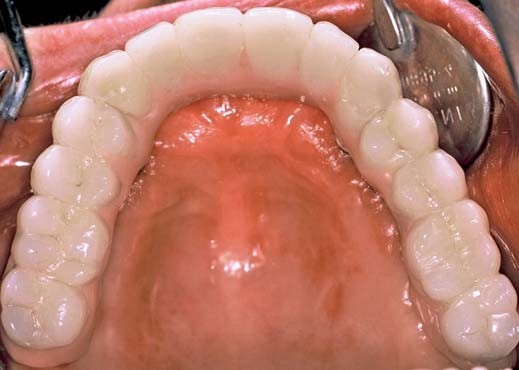
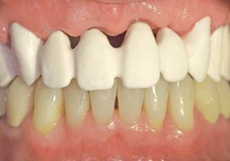
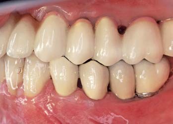
Following multiple extraction of a non-salvageable rest dentition and the placement of six dental implants in positions #4, #5, #6, #11, #12,# 13, a full denture was fabricated. After the extraction sites had healed and denture sores were eliminated, the function and esthetics of the denture was optimized. If necessary, angulations, shape and color of the denture teeth and the shape of the denture base were corrected (Fig. 1a). The resulting denture was used by the patient until the final restoration was delivered. For the final restoration of the maxilla, an implant-retained denture with telescopic crowns as attachments was planned.
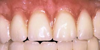
Fig. 1a_Full denture in situ.

Fig. 1b_Duplicate (DentDu) of the interim denture.

Fig. 1c_Trial of the DentDu.
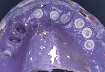
After the implant was uncovered, the denture was modified to allow sufficient space for the healing abutments. A duplicate of the denture (DentDu) was made out of clear resin (Paladur, Heraeus, Hanau, Germany, Fig. 1b). A trial of the DentDu was performed and minor occlusal discrepancies were corrected (Fig. 1c). Bite records were taken in centric occlusion with modeling resin (pattern resin®, GC, Alsip, IL; Fig. 1c), using the casts of the original denture. Afterwards, the DentDu was placed in an articulator and a controlling of the occlusion was made (Fig. 2a) with the bite records. A pickup transfer system con
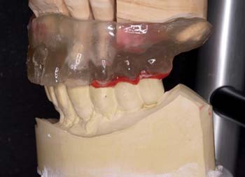
sisting of a titanium impression post and a plastic impression sleeve was employed (Dentegris, Duisburg, Germany, Fig. 2b). The DentDu was carefully modified by creating internal clearance in the area of the implants so that it could be applied as an individualized custom tray. This permitted it to be fully seated when the impression posts were in place. Impressions were generated by a polyether material (Impregum, 3M ESPE, St. Paul, MI). During this process, the DentDu was kept in centric occlusion using the bite records (Fig. 3a).
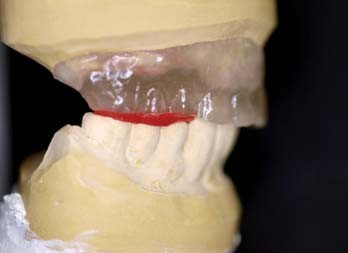
Fig. 2a_Placement of the DentDu in the articulator.
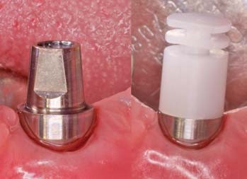
Fig. 2b_Pick-up impression system. On the left: titanium impression post (placed on the implant). On the right: plastic impression sleeve (will be left in the impression).
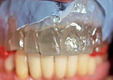
Fig. 3a_Taking the impression with the DentDu. The bite records were used to determine the exact position.
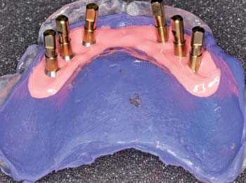
Fig. 3b_Fabrication of the master cast.
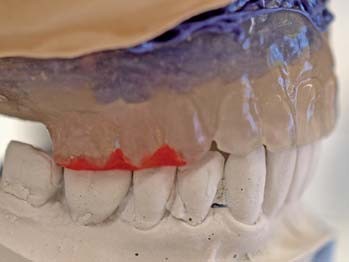
Fig. 3c_Placement of the cast into the articulator using the bite registrations.
The titanium impression posts were connected with the implant analogues and with the plastic impression sleeves (Dentegris), which were embedded in the impression material (Fig. 3b). A master cast was then fabricated and articulated with the help of the bite records (Fig. 3c, Figs. 4a & 4b).
Customizable abutments (Dentegris) were taken to fabricate the implant abutments. Parallelism, angulation, position and shape of the implant abutments were determined using a silicon key fabricated from a matrix of C-silicone (Zetalabor, Zhermack SpA, Badia Polesine, Italy, Fig. 5). The dentist and the dental technician relied on two alternatives for customized abutments selection: 1) UCLA customizable abutments (UCLA, Dentegris) for casting with a gold alloy (for example, Portadur P4, Au 68.50 %, Wieland, Pforzheim, Germany, Fig. 6a) or 2) platinum-iridium customizable abutments (PTIR, Dentegris) for casting with a chromium cobalt (CrCo) alloy (for example, Ankatit, Anka Guss, Waldaschaff, Germany, Fig. 6b).
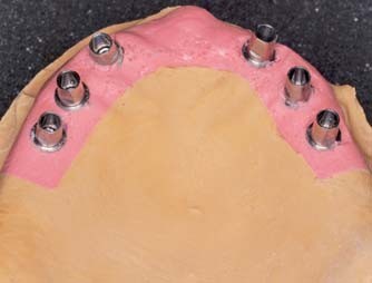
Fig. 4a_Master cast.
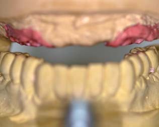
Fig. 4b_The master cast is placed into the articulator.
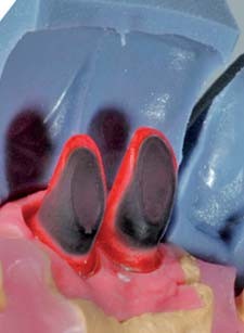
Fig. 5_The customized implant abutments are fabricated using a matrix of C-silicone.
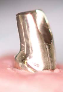
Fig. 6a_Gold customized abutments.
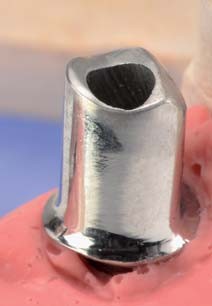
Fig. 6b_Chromium cobalt (CrCo) customized abutments.
After casting, the customized implant abutments were grinded, polished and served as the basis for the
fabrication of electroformed pure-gold copings with a thickness of 0.25 mm (AGC Galvanogold, Au > 99.9%, Wieland, Fig. 6c).2-4 The framework was then constructed via CAD/CAM. To ensure proper functioning of the framework, a plastic mock-up and a temporary fixed denture (TFD) were milled (ZENOPMMA, Wieland). The customized implant abutments, the electroformed copings, the mock-up and the TFD were delivered by the dental laboratory for the next clinical session.
The abutments were transferred, positioned on the implants and torqued to 35 Nm using a resin transfer key (pattern resin, GC; Figs. 7a-b). From this point on, the customized abutments remained fixed in order to avoid any possible inaccuracies. The electroformed copings were placed on the implant abutments (Fig. 7c). The mock-up was placed over the electroformed copings and the occlusion was checked with the bite records (Figs. 8a-b). A final impression with a polyether impression material (Impregum, 3M ESPE) was taken with electroformed copings. The mock-up was further set up and used for the fabrication of a new (final) master cast. After the impression was taken, the TFD was fixed on the implant abutments using temporary cement (TempBond, Kerr, Orange, CA). It was then left in place until the delivery of the final restoration (Fig. 8c).
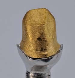
Fig. 6c_Electroformed gold copings.
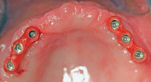
Fig. 7a_The customized abutments are mounted on the implants using a transfer key.
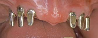
Fig. 7b_The customized abutments are mounted on the implants using a transfer key.
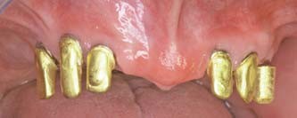
Fig. 7c_Electroformed gold copings in situ.
The new master cast was articulated with the help of the gold copings and the mock-up. The metal framework was milled (here: Titanium Zenotec TI, Wieland, Fig. 9a). The veneering of the superstructure was made using a light-cured indirect ceramic polymer (Ceramage, SHOFU, Menlo Park, CA, Figs. 9a-d). The electroformed gold copings were fixed in the metal framework using a self-curing compomer cement (AGC Cem, Wieland, Fig. 10).
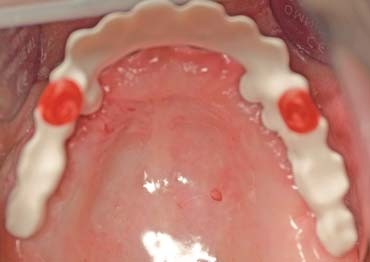
Fig. 8a_Brial of the mock-up.
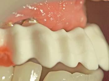
Fig. 8b_Brial of the mock-up.
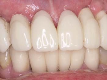
Fig. 8c Temporary fixed denture in situ.
Figs. 9a-d_Final telescopic crown retained implant denture, palatal; (Fig. 9a)
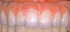
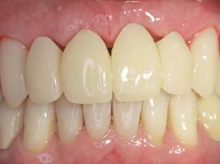
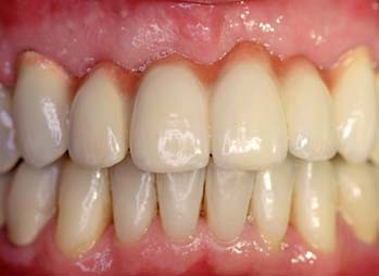
Figs. 9a-d_Final telescopic crown retained implant denture, anterior teeth (Fig. 9b)

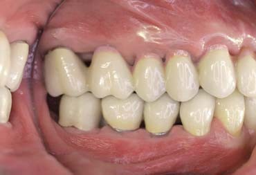
Figs. 9a-d_Final telescopic crown retained implant denture, right side (Fig. 9c),
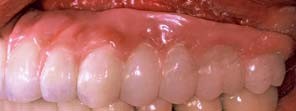
Figs. 9a-d_Final telescopic crown retained implant denture, left side (Fig. 9d).
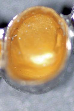
Fig. 10_Placement of the electroformed copings into the frame.
Figs. 11a & b_A case of fixed implant retained denture for the maxilla full-arch rehabilitation: trial of the mock-up (Fig. 11a)
Figs. 11a & b_A case of fixed implant retained denture for the maxilla full-arch rehabilitation: the milled temporary fixed denture is placed on the abutments (Fig. 11b).
The above-described procedures can be also performed in cases in which a fixed denture was planned for the rehabilitation of the full-arch (Figs. 11a & 11b, Figs. 12a-c) and in cases where part of the natural dentition is periodontally stable and can be applied as abutments. In these cases, the immediate full denture can be designed as a cover denture. From this cover denture, a DentDu could be fabricated and further used as described above (Figs. 13a-c).
Figs 12a–c_A case of fixed-implant retained denture for the maxilla full-arch rehabilitation, right site (Fig. 12a)
Figs 12a–c_A case of fixed-implant retained denture for the maxilla full-arch rehabilitation, anterior area (Fig. 12b),
Figs 12a–c_A case of fixed-implant retained denture for the maxilla full-arch rehabilitation, left site (Fig. 12c).
Figs. 13a–c_Impression of a case with natural dentition (teeth #11 and #12) and implants.
Figs. 13a–c_Impression of a case with natural dentition (teeth #11 and #12) and implants. Master cast in the articulator with a duplicate of the over-denture in place (Fig. 13b).

Figs. 13a–c_Impression of a case with natural dentition (teeth #11 and #12) and implants. Gold copings fixed on the remaining teeth #11 and #12 and customized implant abutments mounted on the implants (both of them served as primary telescopes, Fig. 13c).
Porcelain is a possible material for veneering of fixed-denture frameworks. If the angulation of the implants does not allow for taking impressions in the above-described way and an open-tray impression is preferable, fenestrations can be fabricated into the DentDu (Fig. 14).
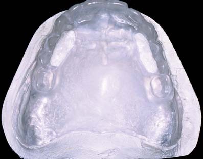
Fig. 14_DentDu modified for opentray impression technique.
Discussion
The reconstruction of the fully edentulous arch with implant-retained dentures necessitates thorough planning and a precise and passive fit of the suprastructure. A previous study demonstrated that a passive fit between the implant superstructure and the underlying abutments is essential for the longterm success of the implant prosthesis.5To achieve a passive fit, an accurate positioning of the implant replicas in the master cast must be assured. The impression technique and the splinting of the implant copings are factors which may contribute to errors in the final positioning of the implant analogs, thus leading to inaccuracies in the fit of the final superstructure.5-10Furthermore, the angulation or proximity of the implants may inhibit proper seating of the impression copings and/or caps, which may also have a detrimental effect on the registration of the implant position.11
The precise recording of the maxillo-mandibular, e.g. interocclusal, relationship is a prerequisite for achieving proper occlusion and a successful treatment outcome.1,10 The initially delivered denture allowed for the correction of the interocclusal relationship, tooth shape and color and angulations during the entire healing period. In this way, the patient was able to acclimatize to the function and esthetics of the denture. In the method described in this report, an accurate impression and recording of the full denture was achieved by using a duplicate as a custom tray for the impression. Therefore, it was not necessary to repeat all the steps usually needed for recording the interocclusal relationship, e.g. wax-up, etc., at the time of the fabrication of the final restoration.
If an open-tray impression is preferred, only minor changes to the procedure are necessary. This method is based on a previous publication.12 In cases such as this, it is advisable to fabricate two DentDus. The impression can be taken by the first DentDu ; the second DentDu is used for the remaining steps. Customized abutments are applied instead of a bar, galvano copings allow a precise transfer coping, and secondary telescopes as well as different technologies are employed for the transfer of implant positions and for the construction of the superstructure.
Customized implant abutments allows for better angulations and shape, for improved occlusal force transmission from the crown to the implant and the bone, and also for facilitating the fabrication of an esthetically pleasing implant-supported denture. Ways in which abutment design contributes to improved esthetics include changes in the location of the crown and changes in the dimension and/or form of the restorative platform.
Additionally, features of the abutment design contribute to the health and dimensional stability of the soft tissue. Current attempts to objectively define implant-restoration esthetics have focused on periimplant mucosal parameters.13,14The introduction of the UCLA abutment provided a custom solution for implant restorations. This direct-to-implant restoration concept provided adaptability. Through waxing and casting, the height, diameter and angulations can be addressed in order to provide a wide range of clinical solutions for problems associated with limited interocclusal distance, interproximal distance, implant angulations and related soft tissue responses.
The customized implant abutments served as primary telescopes, and the electroformed copings served as secondary telescopes in cases where a removable denture with telescopic crowns was used as the attachment. Electroformed gold copings are as sociated with several advantages, in conjunction with both removable and fixed restorations. The galvanoforming and electroforming process yielded a precisely-fitted secondary coping for the implant abutment with a gap of only 12–30 µm. The gold electroformed coping saves space and is made of high-quality material.2-4Using gold copings for the impression allows for the exact transfer of the form, angulations and position of the inserted customized implant abutments.
With the help of the milled mock-up, the future fit of the CAD/CAM fabricated framework can be evaluated and necessary changes in the shape of the restoration and occlusion can be made. Making these changes on the mock-up was easier and less time consuming than making them on the metal framework itself, and it was then possible to transfer them directly to the final framework. Furthermore, the mock-up almost “splinted” the electroformed gold copings during the impression, allowing for the exact transfer of the abutment position. At the same time, the vertical height and interocclusal relationship were recorded. The delivery of a milled temporary restoration permitted a slow and non-progressive loading of the implants, which then leads to bone remodeling.16 Abutments were left in place after mounting. Combined with the fabrication of a new cast, this further decreased the risk of inaccuracies during the transfer process.
Conclusion
The method described here can be used for fullarch restorations with both fixed and removable implant supported dentures. Accurate impressions can be accomplished and occlusion, vertical dimensions, as well as implant positions can be transferred while
facilitating the full-arch restoration process. In addition, this technique resulted in a reduction of the required chair time.
Disadvantages of this technique lie in the fact that the quality of laboratory technician’s work meets higher demands than usual, and that the clinician also needs to acquire some additional skills. Further disadvantages of this method include the need for a highly qualified technical lab and higher technical costs relative to those associated with prefabricated titan implant abutments.
To date, this method has not been applied in conjunction with immediate implant loading. However, dentists and patients have come to expect this level of rehabilitative accuracy, precision, long-term success and aesthetics.
Editorial note: A complete list of references is available from the publisher.
Prof Dr Gregory-George Zafiropoulos
Blaues Haus Sternstr. 61 40479 Düsseldorf, Germany
zafiropoulos@blaues-haus-duesseldorf.de
www.blaues-haus-duesseldorf.de