Streszczenie
Wśród różnych technik znieczulenia coraz większą popularność zyskuje znieczulenie dokostne (transkortykalne). Założeniem tej techniki jest wprowadzenie anestetyku przez blaszkę zbitą bezpośrednio do kości gąbczastej. W odróżnieniu od znieczulenia przezbrodawkowego (doprzegrodowego, typu CIA) umożliwia ono stosowanie anestetyków o dużym stężeniu wazokonstryktora, zapewnia całkowitą „aseptyczność” iniekcji, jak również pozwala na wyeliminowanie następstw pozabiegowych.
Artykuł oparto na badaniu obejmującym 500 znieczuleń transkortykalnych przeprowadzonych przez 3 lekarzy stomatologów. Stanowi on zestawienie parametrów klinicznych iniekcji dokostnych w obrębie szczęki i żuchwy.
Podobnie jak wszystkie techniki znieczuleń, również mechanizm znieczulenia dokostnego opiera się na właściwościach anatomicznych, fizjologicznych i histologicznych tkanek otaczających. Podstawowa zasada działania i dane kliniczne, na których jest ono oparte, pozwalają zakładać, iż technika ta może z powodzeniem zastąpić wszystkie pozostałe.
Możliwości te potwierdzają badania przeprowadzone przez 3 lekarzy stomatologów, którzy wykonali 500 znieczuleń dokostnych (transkortykalnych), podkreślając ich podstawowe zalety:
- Znieczulenie natychmiastowe za pomocą jednej iniekcji kilku (od 2 do 6) zębów zarówno w szczęce, jak i w żuchwie od strony przedsionkowej (bez konieczności dodatkowego znieczulenia od strony językowej czy podniebiennej).
- Wyeliminowanie nieprzyjemnego dla pacjenta zdrętwienia wargi czy policzka.
- Możliwość stosowania, bez ryzyka wystąpienia martwicy, środków znieczulających z dodatkiem wazokonstryktora o dużym stężeniu. Gwarantuje to skuteczność i natychmiastowy efekt przy znieczulaniu zębów dotkniętych zapaleniem miazgi.
- Dlaczego warto stosować znieczulenie dokostne w żuchwie jako technikę podstawową?
- Aby wyeliminować stosowanie znieczuleń przewodowych i uzyskać natychmiastowy efekt znieczulenia (1, 4, 5, 6, 7). Wyjątkiem jest tu chirurgia zatrzymanych zębów mądrości.
- Aby skutecznie i łatwo znieczulić dotknięty zapaleniem miazgi ząb trzonowy w żuchwie (12, 13, 15).
- Aby wyeliminować konieczność dodatkowego znieczulania dziąsła brzeżnego od strony językowej.
- Aby znieczulić za pomocą jednej iniekcji cały odcinek od kła do kła.
- Aby zmniejszyć ilość podawanego środka (1).
Dlaczego należy stosować znieczulenie dokostne w szczęce jako technikę podstawową?
- Aby wyeliminować uczucie opuchnięcia odczuwane przez pacjentów po okołowierzchołkowym podaniu anestetyku (1).
- Aby wyeliminować, nawet w przypadku ekstrakcji, konieczność podniebiennego podania środka znieczulającego, co jest bardzo bolesne dla pacjenta, a ponadto może być źródłem martwicy tkanek miękkich.
- Aby znieczulić jedną iniekcją nawet 4 lub 6 zębów.
- Aby uzyskać natychmiastowy efekt znieczulenia (14).
- Aby zmniejszyć ilość podawanych środków (5).
Wszystkie te korzyści są możliwe do uzyskania i całkowicie zrozumiałe, jeśli zanalizuje się zasady i mechanizmy, na których opiera się znieczulenie doskostne (transkortykalne).
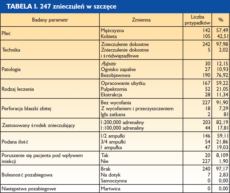
Średni czas wykonania znieczulenia błony śluzowej – 30,04 sekund Liczba cykli rotacyjnych – 2,11
Całkowity czas wykonanie znieczulenia dokostnego – 2 min 29 s Średnia ilość podanego anestetyku: 0,59 ampułki
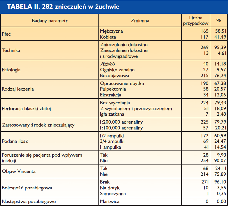
Średni czas wykonania znieczulenia błony śluzowej – 32,74 sekund Liczba cykli rotacyjnych – 3,26
Całkowity czas wykonanie znieczulenia dokostnego – 2 min 46 s Średnia podana ilość anestetyku: 0,59 ampułki

Średni czas wykonania znieczulenia błony śluzowej – 31,39 sekund Liczba cykli rotacyjnych – 2,69
Całkowity czas wykonanie znieczulenia dokostnego – 2 min 38 s Średnia ilość podanego anestetyku: 0,59 ampułki
Znieczulenie dokostne (transkortykalne, śródkostne) polega na iniekcji anestetyku przez blaszkę zbitą do kości gąbczastej otaczającej zęby (8, 11).
Zasada znieczulenia dokostnego sugeruje, iż:
- Znieczulenie jest natychmiastowe, podobnie jak znieczulenie śródwięzadłowe czy przezbrodawkowe (typu CIA, doprzegrodowe).
- Wyeliminowane zostaje obrzmienie czy zdrętwienie tkanek miękkich (policzka lub wargi).
- Liczba znieczulonych zębów jest proporcjonalna do ilości podanego środka (z zastrzeżeniem dotyczącym zmienności osobniczej).
Konieczność stosowania znieczuleń od strony podniebiennej czy językowej można wyeliminować, pamiętając o właściwościach histologicznych i fizjologicznych tkanki kostnej.
Tkanka kostna zbita stanowi strukturę zbudowaną z osteonów, układu blaszek kostnych ułożonych wokół kanałów Haversa. Te ostatnie są wzajemnie połączone za pomocą kanalików poprzecznych Volkmanna, które umożliwiają przenikanie substancji pomiędzy okostną a kością gąbczastą. Dzięki temu podany do kości gąbczastej anestetyk przedostanie się również do okostnej i dziąsła brzeżnego po stronie przeciwnej wobec punktu iniekcji.
Wiadomo ponadto, iż konsekwencje niedotlenienia tkanki zależą od czasu jego trwania. Pamiętając o budowie kości gąbczastej – przestrzeniach pomiędzy beleczkami wypełnionych naczyniami krwionośnymi i ewentualnie tkanką tłuszczową – wnioskujemy, iż podanie anestetyku ze środkiem obkurczającym naczynia nie wywoła efektów równie szkodliwych jak w przypadku ozębnej czy brodawki międzyzębowej (słabo unaczyniona tkanka włóknista).
W konsekwencji technika dokostna dopuszcza stosowanie, bez ryzyka powstania martwicy, środka znieczulającego z wazokonstryktorem o stężeniu 1:100 000 i tym samym rozwiązuje problem natychmiastowego znieczulania zębów z pulpitis.
Wszystkie wymienione dane i parametry kliniczne zachęcają nas, lekarzy, do stosowania tego typu znieczulenia. Oczekujemy bowiem natychmiastowego efektu, większej skuteczności i tym samym rentowności gabinetu oraz wyeliminowania tak nielubianych przez pacjentów skutków ubocznych.
Ograniczenia omawianej techniki wynikają wyłącznie z niemożności perforacji blaszki zbitej (zbyt gruba lub zbyt twarda). W tych rzadkich przypadkach (4%) zalecamy używanie znieczulenia śródwięzadłowego, pamiętając o jego ograniczeniach, m.in. konieczności stosowania anestetyku ze środkiem naczyniozwężającym o stężeniu 1:200 000.
Metody
- Anestetyk: 4% roztwór artykainy z dodatkiem adrenaliny w stężeniu 1:200 000 lub 1:100 000.
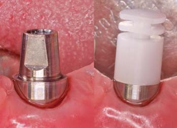
- Igły typu „Transcort” o długości 12 mm i średnicy 0,4 mm.
- Urządzenie umożliwiające perforację – system Quicksleeper.
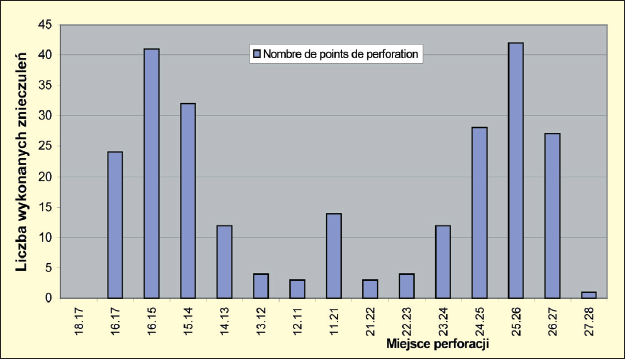
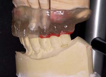
Ryc. 1. Znieczulenia wykonane w szczęce. Analiza punktów perforacji: W szczęce dyfuzja dystalna anestetyku w stosunku do punktu iniekcji wynosi co najmniej dwa zęby. Ta informacja pozwala na podawanie środka w oddaleniu od miejsca pracy. Iniekcja całej ampułki, np. pomiędzy zębem 5 a 6, umożliwia w większości przypadków leczenie w obrębie zębów 7, 6, 5, 4, 3 i 2. Podanie całej ampułki pomiędzy siekaczami centralnymi umożliwia pracę w obrębie odcinka od kła do kła.
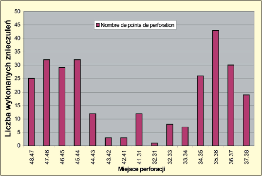
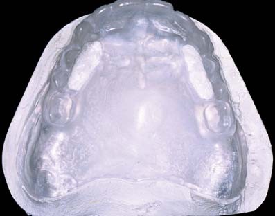
Ryc. 2. Znieczulenia wykonane w żuchwie. Analiza punktów perforacji: W obrębie żuchwy dyfuzja dystalna obejmuje tylko 1 ząb (ze względu na unerwienie i ukrwienie doprzednie), co obliguje nas do maksymalnego zbliżenia punktu iniekcji do zęba lub zębów, które chcemy leczyć. Pamiętajmy, iż nie jest koniczne zawsze dystalne podanie środka. I tak, iniekcja pomiędzy zębem 6 a 7 umożliwi leczenie obu tych zębów. Ponadto należy pamiętać, iż po podaniu dużej ilości środka (całej ampułki) można zaobserwować w 24,11% przypadków znieczulenie okolicy wargowobródkowej. Jednakże w przeciwieństwie do znieczulenia przewodowego do otworu żuchwy czas trwania takiego znieczulenia nie przekracza 100115 godz.
Analiza otrzymanych wyników
Etap pierwszy: komputerowe znieczulenie błony śluzowej.
Etap ten może być całkowicie bezbolesny (nawet bez zastosowania znieczulenia powierzchniowego) pod warunkiem, że lekarz kontroluje w pełni prowadzenie igły (punkty podparcia) i iniekcja jest stopniowa (iniekcja sterowana mikroprocesorowo i uruchamiana za pomocą pedału).
Średni czas wykonania znieczulenia dziąsła brzeżnego wynosi 32 sekundy, bez zastosowania znieczulenia powierzchniowego.
Etap drugi: perforacja blaszki zbitej.
Jest ona również całkowicie bezbolesna, ponieważ blaszka zbita jest nieunerwiona. Liczba cykli rotacyjnych jest wyższa w obrębie żuchwy i wynosi średnio 3,26, a w szczęce jest to 2,11 (1,15). Zjawisko to jest logiczne i wiąże się z różnicami anatomicznymi między szczęką a żuchwą (grubość blaszki zbitej).
Średni czas perforacji twardej blaszki zbitej obliczono, biorąc pod uwagę czas trwania cyklu wynoszący 1 sekundę, podobnie jak czas przerwy pomiędzy cyklami. Daje to łącznie średni czas perforacji twardej blaszki zbitej 5,38 sekund.
W przypadku grubej blaszki zbitej istotnym etapem jest oczyszczenie igły z wiórów kostnych. Pominięcie tej czynności może spowodować ból podczas iniekcji. Podczas wykonanych badań takie oczyszczenie przeprowadzono w 7,29% znieczuleń w szczęce i 18,09% znieczuleń w obrębie żuchwy, co również potwierdza wcześniejsze spostrzeżenia dotyczące różnic anatomicznych między wyrostkiem łuku górnego i dolnego.
Etap trzeci: iniekcja do kości gąbczastej.
Odbywa się ona w sposób powolny, stopniowy i zawsze poniżej progu bólu. Ten ostatni jest indywidualnie zmienny i zależy od gęstości tkanki kostnej. Należy pamiętać, iż kość gąbczasta jest bardzo wrażliwa na nadmierne ciśnienie. W tkance kostnej o dużym stopniu ubeleczkowania konieczna będzie wolniejsza iniekcja. Nadmierne ciśnienie w początkowej fazie wprowadzania anestetyku do kości zbitej spowoduje poruszenie się pacjenta na fotelu (w większości przypadków jest to odruch, któremu nie towarzyszy ból). Z tym objawem spotkaliśmy się w 8,10% znieczuleń w szczęce i 9,93% w żuchwie.
Całkowity czas wykonania znieczulenia zależy od ilości środka znieczulającego i szybkości, z jaką go podajemy. Przeważnie zużywano pół ampułki (średnio 0,59 ampułki). Średni czas wykonania znieczulenia (obejmujący 3 fazy znieczulenia) wyniósł 2 minuty 37 s.
Najczęściej stosowanym w omawianym badaniu anestetykiem była artykaina z dodatkiem adrenaliny o stężeniu 1:200 000 (80,91%), podczas gdy stężenie 1:100 000 zarezerwowano dla zębów dotkniętych zapaleniem miazgi lub też znajdujących się w ogniskach zapalnych (tkanka przekrwiona i o obniżonym pH). Należy zauważyć, iż w 85,26% przypadków iniekcja została wykonana bezpośrednio po perforacji, a więc bez potrzeby cofania igły i jej czyszczenia. W pozostałych przypadkach taką czynność wykonano.
Średni odsetek zatkanych igieł wyniósł 0,81% dla szczęki i 2,48% dla żuchwy, co wiąże się oczywiście z różnicami anatomicznymi. Odsetek igieł, które należało wymienić, był znikomy i wyniósł 1,70%.
Następstwa pozabiegowe
Można je podzielić na dwie kategorie: następstwa natychmiastowe i następstwa wczesne
Następstwa natychmiastowe
Polegają na odczuwaniu przez pacjenta częstoskurczu (tachycardii). Mogłoby to sugerować analogię do podania dożylnego, co w przypadku znieczulenia dokostnego jest technicznie niewykonalne. Występujący częstoskurcz ma charakter przejściowy i pozbawiony jest następstw ogólnych (2, 3, 7, 9). Warto jednak uprzedzić pacjenta o takiej możliwości, aby uniknąć stresu powodującego dodatkowy wyrzut katecholamin endogennych.
Następstwa wczesne
W większości przypadków nie występują, ponieważ znieczulenia błony śluzowej dokonuje się w obrębie masy dziąsłowej, a perforacji – w obrębie masy kostnej. W nielicznych przypadkach następstwa mogą się pojawić przy perforacji grubej blaszki zbitej, w związku z powstającymi wtedy wiórami kostnymi. Powoduje to wystąpienie niewielkiego stanu zapalnego w obrębie dziąsła brzeżnego i bolesność przy dotykaniu. Częstość występowania tego rodzaju powikłań wynosi 3,55% w żuchwie i 2,83% w szczęce (potwierdzenie różnic anatomicznych).
Wnioski
Oprócz zalet klinicznych, takich jak natychmiastowy efekt czy też wyeliminowanie znieczulenia tkanek miękkich, konieczności znieczulenia od strony podniebiennej lub językowej, które nie zostały uwzględnione w tabelach, wyniki tych badań pokazują, iż iniekcja transkortykalna:
- jest skuteczna w 96% przypadków (w 4% jest zastąpiona znieczuleniem śródwięzadłowym);
- charakteryzuje ją średni czas wykonania wynoszący 2 minuty 37 s;
- cechuje się sporadycznymi i niewielkimi efektami ubocznymi;
- nie zakłada konieczności aplikacji dystalnej anestetyku;
- stanowi skuteczną i natychmiastową technikę znieczuleń zębów z zapaleniem miazgi (13,23% badanych) bez jakiegokolwiek ryzyka dla przyzębia.
Dyskusja
Znieczulenie dokostne (transkortykalne) umożliwia, z jednej strony, zmniejszenie ilości podawanego środka (średnio 0,59 ampułki). Ponadto pozwala na natychmiastowe znieczulenie 6 zębów przy podaniu 1 ampułki anestetyku, co daje 0,3 ml na 1 ząb. Czyż więc technika transkortykalna nie jest otwartą drogą do zmniejszenia toksyczności aktu znieczulenia i optymalnego przystosowania tego aktu do zabiegu stomatologicznego?
Autorzy:
- Alain Villette, D.C.D., D.S.O, C.E.S. w dziedzinie biologii jamy ustnej, periodontologii i protetyki Przewodniczący l’Association Francaise pour le Perfectionnement en Anesthesie Dentaire, Praktyka Prywatna, Nantes
- Didier Jallais, D.C.D, Praktyka Prywatna, Francja
- Richard Millette, D.M.D, Praktyka Prywatna, Montreal, Kanada
Przekład: lek. stom. Piotr Kaczmarek, Association de Recherche en Odontologie et Chirurgie Maxillo-Faciale, Paryż
Hasła indeksowe: technika transkortykalna, znieczulenie doprzegrodowe, perforacja blaszki zbitej, natychmiastowy efekt znieczulenia, miejsce perforacji, anestetyk z wazokonstryktorem
Pierwotnie opublikowano w: Magazyn Stomatologiczny, 2004, 6, str. 20-23